29 Ağustos 2015 Cumartesi

OSPF- SHAM Link

Hi Fellas,

Think about 2 customers want you to merge their network over you MPLS network.
You use Layer 3 VPN but customer is informed you about they use methro-ethernet vs. for backup link for their remote sites (backdoor). You think the interface may remain shutdown, but when it is up, it may **** up everythink.

In this case, we will analyze the backdoor-link ;


CE1 ping CE2's loopback address (5.5.5.5) over MPLS network.
Backdoor link is not active !!!!!!

As you can see, 172.23.55.0 network ( PE2-CE2) is learned over 172.23.54.16 (CE1's next hop)
which is so correct.

O IA is , ospf inter area routes :  

Just in case as a reminder:

just O is in OSPF terminology : Intra Area Routes that; sharing routes in the same OSPF domain !

When we activate the backdoor link;

routing table is become like ;


for CE2;

172.23.54.0 (CE1) is learnt over backdoor link !

It by-passed the MPLS network because..........,

there is some "O" front of it !!!!

O is Intra-Area routes that sharing advertises in same OSPF domain,

that when sharing advertises for OSPF calculation,

OSPF always choose INTRA-AREA routes instead INTER-AREA routes.

So we need to throw out some config :)

PE1;

router ospf 2 vrf asd
 log-adjacency-changes
 area 0 sham-link 31.31.31.31 32.32.32.32
 redistribute bgp 1 subnets
 network 172.23.54.0 0.0.0.255 area 0

PE2;

router ospf 2 vrf asd
 log-adjacency-changes
 area 0 sham-link 32.32.32.32 31.31.31.31
 redistribute bgp 1 subnets
 network 172.23.55.0 0.0.0.255 area 0

Regards !

MPLS , TTL Propagate

I switch off the TTL values for between VPN connectivity sites. You need to apply all the MPLS Core routers by one by.

use  no mpls ip propagate-ttl !


Just only exists egress VPN label at PE2 customer toward interface ! 

EIGRP SOO (Site of Origin)

Hi Fellas,

I want to share something about Site of Origin Issue.

So Basicly What is Site of Origin ?? ;

It is used for more focused on loop prevention for  multihomed MPLS customers.
( we can use BGP Cost Community instead, I will share it later...)


CE Routers are connected to PE also they have a back-up link between of them that is we called multihomed in this case.

LOOP !!!!


For clarity, lets diagram this ;

PE advertise routes, and somehow ;

Routes reach CE-R10 towards R8 before going directly CE-R8. When R8 learns about R4's routes from CE-R10, it doesn't install the routes. Instead, from then on it; it prefers to go the " long way around" via PE-R6 and CE -R10

L
O
O
P
!
!


Example ;

CE1 send out the routes, somehow PE1 gets them first before CE2 through backup-link . PE1 at this point sets SOO 1:1 on the EIGRP route then it goes to PE3 > PE2  , PE2 accepts this route because SOO 1:1 different than SOO 2:2. 

Even CE2 is try to re-advertise routes to CE1 ( which is advertised by CE1 ), CE1 won't accept the routes because 1:1 won't let the same ID going in.

Note that;

PE2 does not re-write the tag from 1:1 to 2:2. Tags are only written if they are missing, they are never re-written.


I configure SOO 1:1 on Site A , SOO 2:2 on Site B ;

Routes leave site A will be tagged with 1:1 and routes leave site B will be tagged with 2:2

Site a will accept Site B2s routes and Site B will accept Site A's routes , but Site A won't accept it's own routes back in on the "border" routers


The network connection seems ok, CE1 can ping CE2's loopback address (Backdoor link is shutdown for testing purpose only that MPLS works)


And we see 5.5.5.0/24 prefix next hop address is 10.10.10.2 which uses through backdoor link !

PE1 

interface FastEthernet0/0
 ip address 172.23.54.15 255.255.255.0
 delay 100
 duplex auto
 speed auto
!
interface FastEthernet1/0
 bandwidth 100
 ip address 10.10.10.1 255.255.255.0
 delay 10000000
 duplex auto
 speed auto
!

I change default delay settings that CE1 prefixes (for 5.5.5.0/24 ) is forwarded to PE1 instead of backdoorlink.


And as I mentioned before, that could create loop for our  MPLS network grid. ! We will use SOO ;

PE 1

route-map SOOx permit 10

 set extcommunity soo 1:1
!
interface FastEthernet0/0
 ip vrf forwarding asd
 ip vrf sitemap SOOx
 ip address 172.23.54.16 255.255.255.0
 duplex auto
 speed auto


So0 is 1:1 now :) No worries for loop issue again :D


28 Ağustos 2015 Cuma

RIB-Faiure (17) in VPNV4

Hi Fellas,

You can face with RIB-Failure frequently when your advertised routes have better AD than BGP AD or MP-BGP AD


For this case;


When we quick look at VPNv4 routing table on R4 ;
172.23.54.0 network which next-hop is 2.2.2.2 so this case 
R2's customer towards interface (fastEthernet0/0) caused a RIB-Failure.

Because,
I believe that R2 fa 0/0 and R4 fa 1/0 is sharing both 172.23.54.x prefixes, when
I change R2 > fastEthernet0/0 ospf cost 400


Gratz !

Additionally , OSPF AD 110, IBGP 200, EBGP 20 

RIP into MPLS Redistribution

Hi Fellas,

I want to share with you some little small hint for this MPLS topology


ip vrf asd
 rd 1:100
 route-target export 1:100
 route-target import 1:100
!
!

!router ospf 1
 log-adjacency-changes
 network 0.0.0.0 255.255.255.255 area 0
!
router rip
 version 2
 !
 address-family ipv4 vrf asd
  redistribute bgp 1 metric transparent
  network 10.0.0.0
  no auto-summary
  version 2
 exit-address-family
!
router bgp 1
 no synchronization
 bgp log-neighbor-changes
 neighbor 4.4.4.4 remote-as 1
 neighbor 4.4.4.4 update-source Loopback0
 no auto-summary
 !
 address-family vpnv4
  neighbor 4.4.4.4 activate
  neighbor 4.4.4.4 send-community both
 exit-address-family
 !
 address-family ipv4 vrf asd
  redistribute rip
  no synchronization
 exit-address-family

without "transparent" word when we try to redistribute rip over bgp , advertised prefixes are not adverties properly.

Cisco says:

Make sure that a metric, whether a specific metric or the keyword transparent, is configured when redistributing MP-BGP routes into RIP. If one is not specified, the routes may not be redistributed.

Regards !

26 Ağustos 2015 Çarşamba

VRF - Lite

Lets small step to core MPLS network, but it is not so core at all :)

It is  called VRF - Lite that VRF concept without MPLS by Cisco ,

 There are guest and trusted internet access for an enterprise;

VLAN 10 - 10.x.x.x Network is used for trusted > VRF BUE
VLAN 20 - 192.x.x.x Network is used for guest network  > VRF RED


R1 :

outer ospf 1 vrf BLUE
 router-id 0.0.1.1
 log-adjacency-changes
 network 10.0.0.0 0.0.255.255 area 0
 default-information originate
!
router ospf 2 vrf RED
 router-id 0.0.1.2
 log-adjacency-changes
 redistribute static metric 10 subnets
 network 192.168.0.0 0.0.255.255 area 0
 default-information originate
!
ip route vrf BLUE 0.0.0.0 0.0.0.0 10.0.0.1
ip route vrf RED 0.0.0.0 0.0.0.0 192.168.0.1
 
 
R2 : 
 
router ospf 1 vrf BLUE
 router-id 0.0.2.1
 log-adjacency-changes
 network 10.0.0.0 0.0.255.255 area 0
!
router ospf 2 vrf RED
 router-id 0.0.2.2
 log-adjacency-changes
 network 192.168.0.0 0.0.255.255 area 0
!
 
R3: 
 
router ospf 1 vrf BLUE
 router-id 0.0.3.1
 log-adjacency-changes
 network 10.0.0.0 0.0.255.255 area 0
!
router ospf 2 vrf RED
 router-id 0.0.3.2
 log-adjacency-changes
 network 192.168.0.0 0.0.255.255 area 0
!
end


PS 1 : Also don't forget to configure proper ospf routing R4 and R5 with vrf configs.
With ospf routing we have full connectivity between OSPF domain like MPLS core !

PS : The PC's at access circuit are routers actually :)

PS 2: I share an example for one of them ;

At R3 ; 

router ospf 10 vrf BLUE
network 10.0.0.0 0.0.255.255 area 0

PC3:
router ospf 10
network 10.0.0.0 0.0.255.255 area 0

R3 and PC3 is ospf neighbour now !

Lastly ;
we need to redistribute OSPF 1 into OSPF 10 and vice versa ;

R3:
router ospf 1 vrf BLUE
redistribute ospf 10 vrf BLUE subnets      

router ospf 10 vrf BLUE
redistribure ospf 1 vrf BLUE subnets

Now, P3 is full connectivity with R5 that is default gateway for trusted networks.


Cisco VPLS 2

This post is a continuation of MPLS L2VPNs since it’s describing MPLS VPLS running on the top of the same LDP infrastructure.

Well a disadvantage of MPLS L2VPN is scalability in configurations where you need to connect more than two sites since L2VPNs is  a point-to-point technology. Creating more and more L2VPNs might be a bit complicated and time consuming especially in case of troubleshooting MPLS L2VPN problems.
To solve these problems VPLS was created and  yeeeeees (!!)  is that it’s a point-to-multipoint technology.
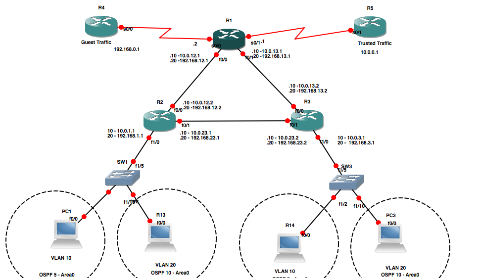
Imagine that you need to span a VLAN across three Data Centers in different localizations and you own the core network connecting all sites. What you need is VPLS that will simply create a “cloud hub” thanks to MPLS running in your core. Here’s an example topology:

This article describes a simple and effective VPLS configuration running on LDP used for L2VPN in previous article.
On that note, I will mention that there is another way of implementing VPLS based on MP-BGP. This method is a little bit more complicated and involves upgrading your iBGP configuration; however, it’s automated to a point where you don’t have to defines all neighbours of a VPLS to create a full mesh (as described below) and requires defining VPN ID only (it’s using build-in auto-discovery to automatically create the full mesh).

In my opinion, both MPLS technologies meaning L2VPNs and VPLS based on LDP are extremely easy to implement and provide really cost effective way of tunnelling traffic through your network!


Steps 1. Configuring Provider router (P router) configuration - routers building the core
– Enabling LDP protocol which is responsible exchanging label mapping information’s between Label Switch Routers (LSR):
mpls label protocol ldp
– Forcing Router-ID of LSR to loopback:
mpls ldp router-id Loopback0 force
– Enabling MPLS on needed interfaces:
mpls ip
Changing MTU on interfaces running MPLS:
mtu 1564
Double labeling needs to be added to an MPLS frame on PE router. The first one is used for label switching and the second one carries the L2VPN label. MTU 1564 allows to q-in-q tunnels to be carried over L2VPNs.
– Enabling CEF if not on by default.


Step 2. Configuring Provider Edge router (PE router) configuration – these router/L3 switch are found on a MPLS edges. They are responsible for adding and removing MPLS tags. Because of it, these handling these packets will be using more hardware performance and if not taken care of in hardware this might increase the CPU utilisation (example C7200s).
As described above enabling LDP on a router:
mpls label protocol ldp
mpls ldp logging neighbor-changes
mpls ldp router-id Loopback0

Under MPLS enabled interfaces:
mpls ip
mtu 1564

To create a VPLS tunnel, PEs are defining “l2 vfi” that include all the VPLS tunnel configuration. They are attached to VLAN interfaces, using xconnect command (similarly to L2VPN) and finally as you can imagine, all is being added to a physical interface as described below.
Defining VPLS VLAN ID and its neighbours:
l2 vfi l2vpn manual
vpn id 1
neighbor 10.0.0.2 encapsulation mpls
neighbor 10.0.0.3 encapsulation mpls
neighbor 10.0.0.4 encapsulation mpls

Attaching l2 vfi to VLAN using xcommand:
interface Vlan2
no ip address
xconnect vfi l2vpn

Attaching VLAN 2 to an interface:
interface FastEthernet4/2
no ip address
switchport
switchport trunk encapsulation dot1q
switchport mode trunk

Step 3. Configuring L2 switches
These switches are used to provide more ports for other potential VPLS VPNs while saving ports on your PEs.
Link connecting PE with a L2 switch is a trunk.
Other L2 switch ports are used to connect customer’s/network devices to VPLSs.
Configuration of this switch is omitted since defining one trunk and a number of access ports shouldn’t be a problem.
Troubleshooting:
– Make sure that the CEF is enabled on all P and PE routers
– Make sure that MPLS and corrct MTU is enabled on all required interfaces
– Make sure that all CE have C configuration plus VFI configuration
– Confirm consistency of th MPLS VPN tag and basic port configuration
– For the status of the VPN per neighbor do:
sh mpls l2 vc
– To check the MPLS table and confirm that the traffic is not being blackholed do:
sh mpls forwarding-table
– To check VFI info’s do:
sh vfi..
– To check next hop details by label do:
sh xconnect all details —- check remote labels of the next hops
sh mpls forwarding-table labels xxx —- confirm next hop neighbor

VPLS LAB 1 - Example

Before you configure VPLS, you need to ensure that IP routing and MPLS forwarding are configured properly and that the minimal Layer 2 VPN connectivity requirements

Every PE router has a loopback interface that is configured with an IP address and a /32 network mask >  Router ID in LDP signaling for the PE router.

PE routers have IP connectivity to each other >  LDP Neighborship

PE routers have MPLS label switched paths (LSPs) for those host route > Activate MPLS Routing


Attachment circuits that are used in VPLS can be Layer 2 switch-port interfaces, Gigabit Ethernet interfaces on intelligent line cards, or other interfaces with bridged encapsulation.

Before going into the configuration steps for Layer 2 switchport interface, it is necessary to explain the difference and the correlation between a service-delimiting VLAN tag and an internal VLAN tag


Service providers use service-delimiting VLAN tags to identify different types of customer traffic. Because a service-delimiting VLAN tag usually has only local significance, it is removed at the ingress PE router. The egress PE router might have a different service-delimiting VLAN tag, which is added to the packets that are sending to a CE router.


An internal VLAN tag identifies a bridge domain on a PE router. In the context of VPLS, it is the virtual switch.
 Conceptually, service-delimiting VLAN tags and internal VLAN tags are two independent entities.

A port can operate in 3 different modes as:

Access :The interface sends and accepts untagged Ethernet packets only. Tagged Ethernet VLAN packets are dropped.

interface FastEthernet4/3
 no ip address
 switchport
 switchport access vlan 2
 switchport mode access


 Trunk : The interface sends and receives tagged Ethernet VLAN packets and native VLAN packets.

 interface FastEthernet4/3
 no ip address
 switchport
 switchport trunk encapsulation dot1q
 switchport trunk allowed vlan 2-10
 switchport mode trunk


Dot1q Tunnel : Any packet, tagged or untagged, is forwarded through a QinQ tunnel. A QinQ tunnel is identified by the access VLAN tag that is configured on the Layer 2 switchport interface. The access VLAN tag is added to the packet at the ingress tunnel interface and removed at the egress tunnel interface, which means that the VLAN tags must be identical at both interfaces for a given QinQ tunnel.


QinQ tunneling is an Ethernet native tunneling mechanism that stacks VLAN tags together in a similar fashion to the MPLS labels. The outer VLAN tag that is added at the tunnel ingress interface is the access VLAN tag that is configured on the Layer 2 switchport interface. The purpose of the outer VLAN tag is similar to that of the tunnel label in an MPLS-encapsulated pseudowire packet. The outer VLAN tag is to forward the packet from the ingress tunnel endpoint to the egress tunnel endpoint and hide the inner VLAN tag from the transit network.
In VPLS, the transit network is an MPLS network, and a tunnel label is used to move packets from the LSP ingress endpoint to the egress endpoint. Because the function of an outer VLAN tag is effectively replaced by an MPLS tunnel label, the outer VLAN tag is no longer added to the Ethernet header when the Layer 2 switchport interface is configured as dot1q-tunnel mode. That is the main difference in the way dot1q-tunnel mode operates in VPLS versus normal bridging.


The main difference is dot1q tunneling and VPLS mechanism is ;
the outer VLAN tag is replaced with MPLS Tunnel Labels !!!!! 


 interface FastEthernet4/3
 no ip address
 switchport
 switchport access vlan 2
 switchport mode dot1q-tunnel


Configuring VFI : 

We need mapping mechanisim like ( Frame Relay = DLCI, ATM= PVC etc)

In this case;

VPLS = VFI
Also VFI needs some VPN ID.

l2 vfi blue manual
 vpn id 100
 neighbor 10.0.0.2 encapsulation mpls
 neighbor 10.0.0.3 encapsulation mpls

 neighbor 10.0.0.4 encapsulation mpls


Associating Attachment Circuits to the VFI:

The final step is building the many-to-many mapping involves how to associate attachment circuits to a VFI in configuration.


 Step 1.
  VPLS-PE1(config)#interface vlan 2


Note that the VLAN ID needs to be identical to the service-delimiting VLAN tag when using Layer 2 switchport trunk mode. Otherwise, it can be the tag value of an unused VLAN.

Step 2.
Attach the VFI to the VLAN interface:

  VPLS-PE1(config-if)#xconnect vfi blue


CE1 sends and receives untagged Ethernet packets, null service-delimiting VLAN tags.
PE1 configures the switchport mode as dot1q-tunnel to forward packets that have an unmodified Ethernet header. 


The internal VLAN that is associated with the switchport is 2.


CE2 sends and receives tagged Ethernet VLAN packets of which the service-delimiting VLAN tag is 4. PE2 configures the switchport mode as a trunk to remove or add the service-delimiting VLAN tag accordingly. The internal VLAN that is associated with the switchport is 4.

CE3 sends and receives untagged Ethernet packets that, null service-delimiting VLAN tags. PE3 configures the switchport mode as access to forward all untagged packets. The internal VLAN that is associated with the switchport is 8.

CE4 sends and receives tagged Ethernet VLAN packets of which the service-delimiting VLAN tag is 10. PE4 configures the switchport mode as a trunk to remove or add the service-delimiting VLAN tag accordingly. The internal VLAN that is associated with the switchport is 10.


hostname PE1
!
mpls label protocol ldp
mpls ldp logging neighbor-changes
mpls ldp router-id Loopback0
!
l2 vfi l2vpn manual
 vpn id 1
 neighbor 10.0.0.2 encapsulation mpls
 neighbor 10.0.0.3 encapsulation mpls
 neighbor 10.0.0.4 encapsulation mpls
!
interface Loopback0
 ip address 10.0.0.1 255.255.255.255
!
interface POS3/1
 ip address 10.0.1.1 255.255.255.252
 mpls ip
!
interface FastEthernet4/2
 no ip address
 switchport
 switchport access vlan 2
 switchport mode dot1q-tunnel
!
interface Vlan2
 no ip address
 xconnect vfi l2vpn

PE2 --

hostname PE2
!
mpls label protocol ldp
mpls ldp logging neighbor-changes
mpls ldp router-id Loopback0
!
l2 vfi l2vpn manual
 vpn id 1
 neighbor 10.0.0.1 encapsulation mpls
 neighbor 10.0.0.3 encapsulation mpls
 neighbor 10.0.0.4 encapsulation mpls
!
interface Loopback0
 ip address 10.0.0.2 255.255.255.255
!
interface POS3/1
 ip address 10.0.2.1 255.255.255.252
 mpls ip
!
interface FastEthernet4/2
 no ip address
 switchport
 switchport trunk encapsulation dot1q
 switchport trunk allowed vlan 4
 switchport mode trunk
!
interface Vlan4
 no ip address
 xconnect vfi l2vpn

PE3

hostname PE3
!
mpls label protocol ldp
mpls ldp logging neighbor-changes
mpls ldp router-id Loopback0
!
l2 vfi l2vpn manual
 vpn id 1
 neighbor 10.0.0.1 encapsulation mpls
 neighbor 10.0.0.2 encapsulation mpls
 neighbor 10.0.0.4 encapsulation mpls
!
interface Loopback0
 ip address 10.0.0.3 255.255.255.255
!
interface POS3/1
 ip address 10.0.3.1 255.255.255.252
 mpls ip
!
interface FastEthernet4/2
 no ip address
 switchport
 switchport access vlan 8
 switchport mode access
!
interface Vlan8
 no ip address
 xconnect vfi l2vpn

Example 15-8 shows the configuration on PE4.

Example 15-8. PE4 Configuration

hostname PE4
!
mpls label protocol ldp
mpls ldp logging neighbor-changes
mpls ldp router-id Loopback0
!
l2 vfi l2vpn manual
 vpn id 1
 neighbor 10.0.0.1 encapsulation mpls
 neighbor 10.0.0.2 encapsulation mpls
 neighbor 10.0.0.3 encapsulation mpls
!
interface Loopback0
 ip address 10.0.0.4 255.255.255.255
!
interface POS3/1
 ip address 10.0.4.1 255.255.255.252
 mpls ip
!
interface FastEthernet4/2
 no ip address
 switchport
 switchport trunk encapsulation dot1q
 switchport trunk allowed vlan 10
 switchport mode trunk
!
interface Vlan10
 no ip address
 xconnect vfi l2vpn
After full connectivity is established among all CE routers, every PE router should learn all MAC addresses from the CE routers.